Auxiliary Lights Dim Under Load: Diagnose Voltage Drop, Relay and Ground Faults
An auxiliary light that looks normal with the engine off but dims, flickers or drops out on the road does not automatically need a new lamp. The useful first step is to reproduce the symptom with the circuit carrying its real load, then measure where voltage is being lost.
Keep the factory lighting circuit separate from the diagnosis. Federal lighting requirements in FMVSS 108 apply to required lamps and associated equipment. An accessory repair should not disable, obscure or casually splice into those required functions. Use the vehicle wiring information for the exact model and have uncertain integrations reviewed by a qualified automotive electrician.
Start with the symptom, not the replacement part
Write down exactly when the fault appears: one lamp or both, low or high engine speed, dry or wet weather, after several minutes, only with a winch or blower running, or only when the truck moves. Confirm the battery terminals are secure and the charging system has no obvious warning. Inspect the accessory harness for pinched insulation, unsupported splices, heat-darkened fuse holders, loose relay sockets and grounds attached over paint or rust.
Do not upsize a fuse to keep the circuit alive. Switch the accessory off before opening a fuse holder or moving a connector, keep tools clear of rotating components, and protect the meter leads from the fan and belts. If insulation is melted, a wire is hot, smoke is present or the circuit protection has been bypassed, stop the test and isolate the circuit.
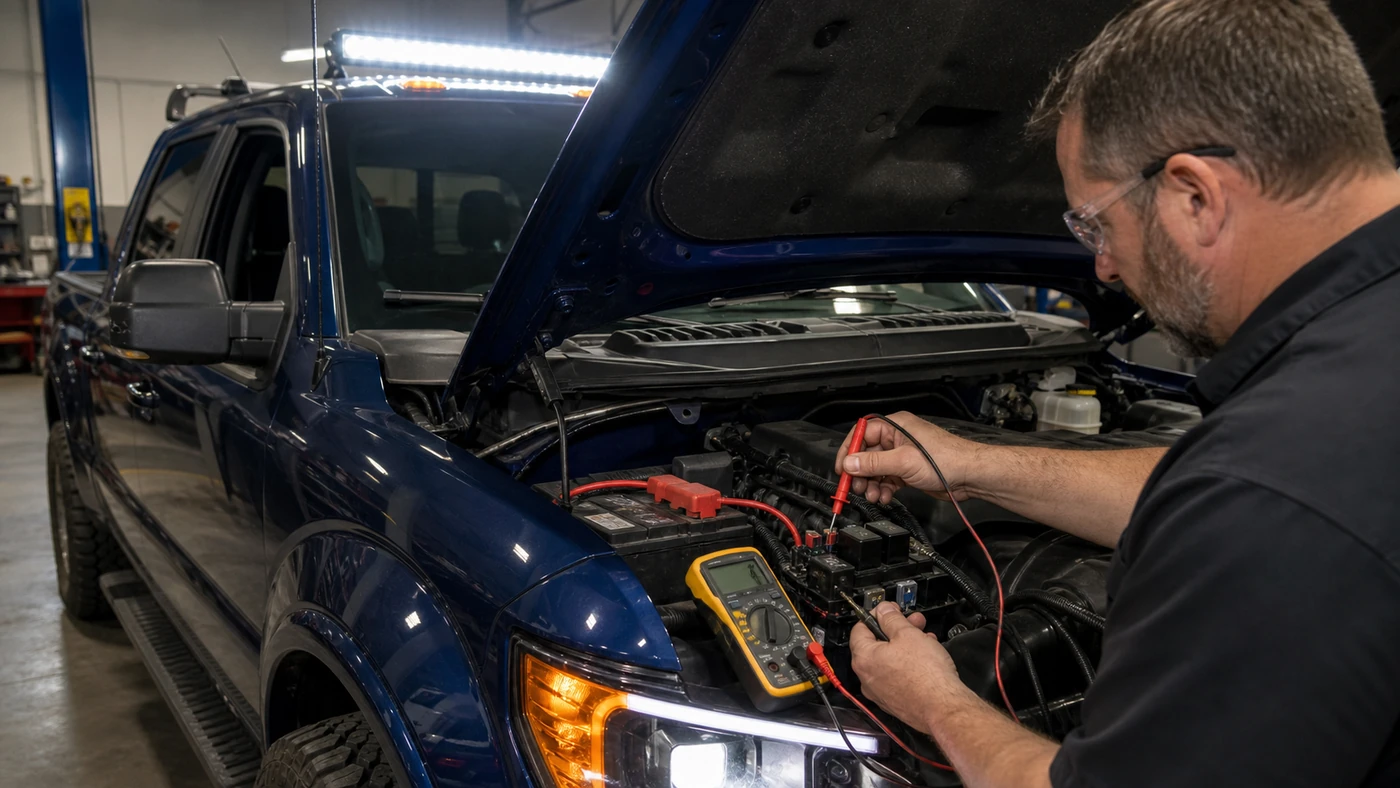
Measure the feed side while current is flowing
A resistance check on an unpowered wire can miss a connection that fails only under load. The Fluke automotive voltage-drop guide explains why the circuit must be operating for this test to expose a restriction. Set a suitable digital multimeter to DC volts, switch the auxiliary lights on, and measure across one section at a time rather than guessing from battery voltage alone.
- Battery positive to fuse input
- A reading here points to loss in the battery connection, supply cable or an upstream junction.
- Across the fuse and holder
- Voltage across a closed fuse path means the fuse blades, clips or holder are adding resistance.
- Relay supply to relay output
- Loss across energized contacts separates a relay-contact problem from a downstream harness fault.
- Relay output to lamp positive
- A rise in this section directs the inspection to the long harness, connectors, splices and lamp plug.
Compare the readings with the vehicle and component service information instead of treating one internet number as universal. Wire length, current, connector count and circuit design all matter. The practical method is to divide the path until the large part of the loss is isolated, repair that exact section, and repeat the same loaded measurement.
Prove the ground path separately
A bright test light clipped to a convenient body bolt does not prove that the lamp’s ground can carry its normal current. Leave the accessory on and measure from the lamp ground terminal toward battery negative in sections. Check the lamp connector, ground lead, ring terminal, mounting surface, body-to-frame path and battery ground. A reading that jumps when the harness is moved can reveal a loose crimp or broken conductor hidden under insulation.
Remove paint, corrosion and looseness only at a verified ground point, then restore the surface and fastener using the vehicle or accessory maker’s method. Do not create a new ground near fuel or brake lines, airbag wiring, high-voltage hybrid components or unknown factory harnesses. After the repair, secure the cable so vibration and sharp edges cannot recreate the fault.
Let the fuse and relay evidence agree
A relay can click and still have burned contacts. A fuse can look intact and still sit in a heat-damaged holder. Match the relay terminal layout and current rating to the documented circuit, then inspect the socket for spread terminals or discoloration. If a known-good relay is used as a test, it must have the same pin arrangement and specification; similarity of the plastic case is not proof.
Fuse choice also depends on normal current, inrush, ambient temperature, conductor capacity and the interrupting needs of the circuit. The manufacturer’s Littelfuse Fuseology design guide lists those factors as part of proper selection. A larger fuse is not a cure for heat at a connector or a shorted harness. If the correct fuse opens again, keep the circuit off until the cause is found.
Close the job with the same loaded test
Repair only the section that failed, using automotive wire, sealed connectors and support appropriate to the location. Route the harness away from exhaust heat, steering movement, suspension travel and abrasion. Reinstall covers and weather seals, then switch on the same electrical loads that originally exposed the problem.
- record battery voltage and the original feed-side and ground-side drops;
- repeat each measurement after the repair with both lamps operating;
- confirm steady brightness at idle and with normal accessories switched on;
- check the harness by steering, moving the vehicle safely and gently flexing accessible connectors;
- inspect the fuse holder, relay and repaired joint again after a short operating period.
The repair is complete only when the symptom is gone and the second loaded measurement proves the voltage is reaching the lamp through both a sound feed and a sound ground.